Pressure Regulator Explained (I) : The Construction of Pressure Regulators
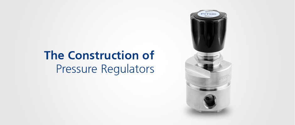
What are Pressure Regulators?
In industrial fluid systems, maintaining stable pressure control is critical to safe system operation. Pressure regulators reduce high inlet pressure and stabilize it at a lower level as demanded, and respond to outlet pressure changes to maintain or control the desired system pressure.

Basic Components
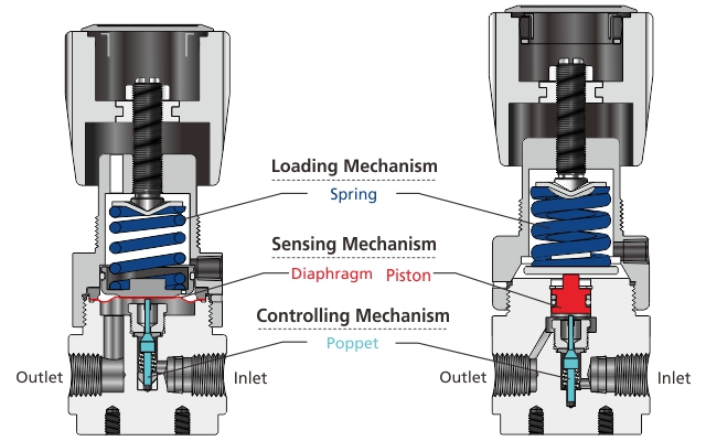
Figure 1 Construction Diagram of Pressure Regulators
Loading Mechanism
The loading mechanism functions to apply a downward loading force from the top of the pressure regulator. FITOK pressure regulators adopt the spring-loaded mechanism, which is most widely used in pressure regulators for its reliability and low cost, and the loading force can be adjusted by compressing the spring with the operating handle.
Sensing Mechanism
The sensing mechanism allows the poppet to rise and fall after sensing the outlet pressure changes of the pressure regulator. Diaphragms and pistons are two typical sensing mechanisms. A diaphragm is usually used for low-control, pressure sensitive high purity applications such as the semiconductor industry. FITOK Hastelloy diaphragm sensing mechanism ensures excellent sensitivity and set point pressure stability. A piston cannot be used in high purity applications due to the restriction of O-ring seal, but can be used to regulate higher pressures for its higher pressure bearing capacity than a diaphragm. The piston sensing mechanism is also more resistant to peak pressure damage and has a short stroke, thus maximizing cycle life.
Controlling Mechanism
The controlling mechanism acts to reduce a higher inlet pressure to a lower outlet pressure, and the main component of the controlling mechanism is the poppet. Through the movement of the poppet toward or away from the seat, the flow area within the regulator can be adjusted to realize the purpose of reducing fluid pressure to the desired outlet pressure. In diaphragm pressure regulators, there are two types of pressure regulators— free poppet and tied diaphragm, depending on whether the poppet is connected to the diaphragm. For the free poppet construction, the poppet is only in contact with the diaphragm when the outlet pressure is equal to or lower than the set pressure. However, for the tied diaphragm design, the diaphragm and poppet are mechanically connected, and when the outlet pressure rises above the set pressure, the diaphragm flexes upward to pull the poppet moving upward, thus achieving “Positive Shut-off” for better body seal and added safety. In addition, FITOK tied diaphragm pressure regulators are designed with no threads or springs in the wetted area to improve system cleanliness, which are applicable for ultra high purity applications.
It should be noted that tied diaphragm regulators should not be used as shut-off valves or shut-off devices even though they can achieve Positive Shut-off.
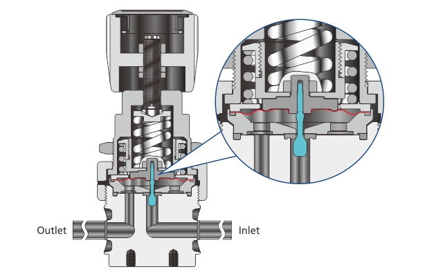
Figure 2 Tied Diaphragm Pressure Regulators

Pressure Regulator Working Principle
When a regulator is in operation, three basic components work together to achieve the desired pressure control. The sensing mechanism senses the inlet pressure (Fi)) and outlet pressure (Fo), and then tries to achieve a balance with the loading force (Fs) from the loading mechanism, i.e. Fi+Fo=Fs to reach an equilibrium. When the inlet pressure (Fi) reduces, the constant downward loading force (Fs) will push the poppet moving away from the seat. In this case, the flow area will become bigger and lead to a decrease of the flow rate, resulting in the outlet pressure (Fo) rise and thus achieving the balance again. Therefore, pressure regulators can keep the outlet pressure stable within a certain range.
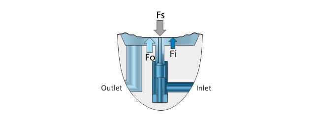
Figure 3 Pressure Control Diagram of Pressure Regulators

Pressure Regulators and Back Pressure Regulators
Back pressure regulators function similarly as pressure regulators, i.e. they both balance the upward force from the fluid system and the downward force from the loading mechanism.
The difference between back pressure regulators and pressure regulators is mainly in the application: pressure regulators control outlet pressure, while back pressure regulators control inlet pressure. Typically, pressure regulators are installed before system media reach the main process and control the pressure to the process by sensing the outlet pressure and controlling their own downstream pressure, while back pressure regulators are installed where system pressure is higher than desired and control the pressure from the process by sensing the inlet pressure and controlling the pressure from upstream.
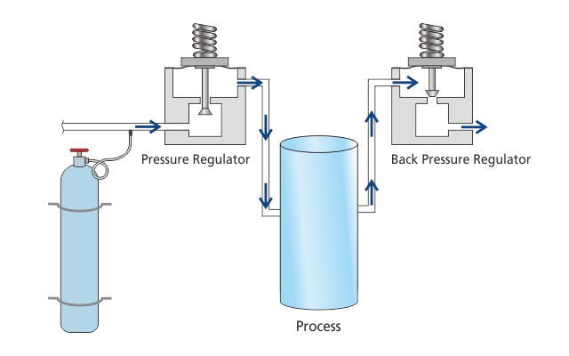
Figure 4 Working Condition Diagram of Pressure Regulators and Back Pressure Regulators
Conclusion
Pressure regulators are mainly used to maintain a relatively constant outlet pressure even though there is pressure fluctuation from the inlet. Components with different designs and made of different materials are applicable to your varying working conditions. In addition, learning the knowledge of how to choose a pressure regulator and how to use a pressure regulator flow chart will further contribute to your right selection of a pressure regulator for the fluid systems.
For more information about pressure regulators, please see Pressure Regulator Selection Guide and Full Technical Catalog for Specialty Gas Application. If you have any questions, please contact us directly and We will reach you soon.
Related Articles:


.jpg)
.jpg)
 Back
Back 