


.jpg)
.jpg)
 Back
Back Pressure Regulator Explained (V) : Glossary of Terms for Pressure Regulators
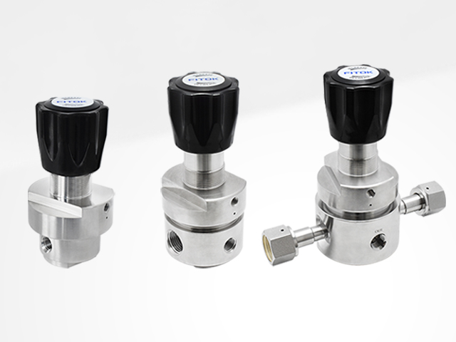
Pressure Regulators: A pressure regulator is a device that reduces inlet pressure to a desired outlet pressure and works to maintain the outlet pressure, even with changes in medium conditions, such as fluctuations in the inlet pressure. It is widely used in various pipeline systems. A pressure regulator is not a shut-off valve and should not be used as a shut-off device.

Construction
Load Mechanism: Used to apply a downward loading force from the top of a pressure regulator to set the outlet pressure of a pressure regulator. FITOK pressure regulators are primarily spring-loaded. Refer to Pressure Regulator Explained (I): The Construction of Pressure Regulators for details.
Sensing Mechanism: Detects changes in outlet pressure and allows the lift poppet to move upward or downward, maintaining force equilibrium inside the regulator. There are three types of sensing mechanisms: piston, diaphragm and bellows (Figure 1). Refer to Pressure Regulator Explained (I): The Construction of Pressure Regulators for details.
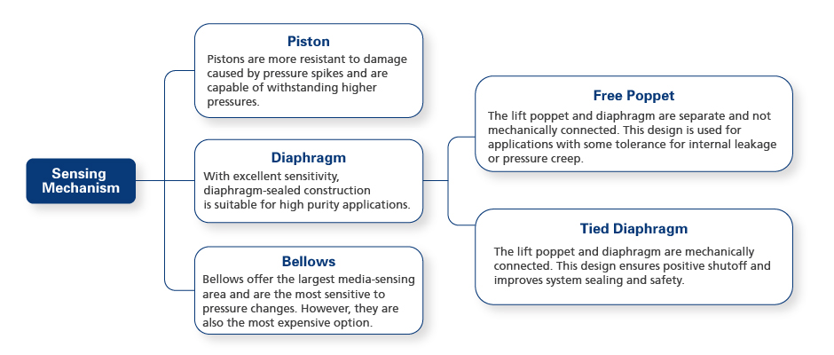
Figure 1 Sensing Mechanism Types
Control Mechanism: Reduces the high inlet pressure to a lower outlet pressure and maintain a stable outlet pressure by adjusting the flow area through the downward and upward movement of the lift poppet. Refer to Pressure Regulator Explained (I): The Construction of Pressure Regulators for details. Figure 2 illustrates the structures of pressure regulator with different sensing mechanisms.
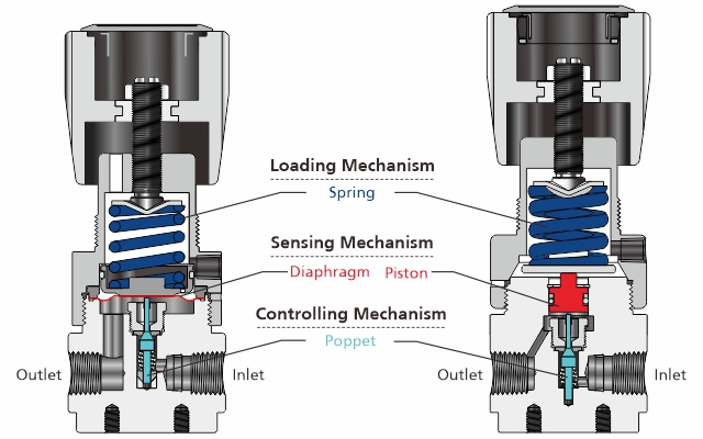
Figure 2 Pressure Regulator Structures
Unbalanced Poppet: The most common lift poppet design, where the inlet pressure provides the main loading force (pushing the lift poppet toward the seat). This design is affected by fluctuations in the inlet pressure, resulting in a noticeable Supply Pressure Effect (SPE).
Balanced Poppet: The special construction design reduces the proportion of inlet pressure as the loading force, resulting in a less noticeable Supply Pressure Effect (SPE) compared to the unbalanced poppet. As shown in Figure 3, the balanced port design represents a key difference between the two poppet types.
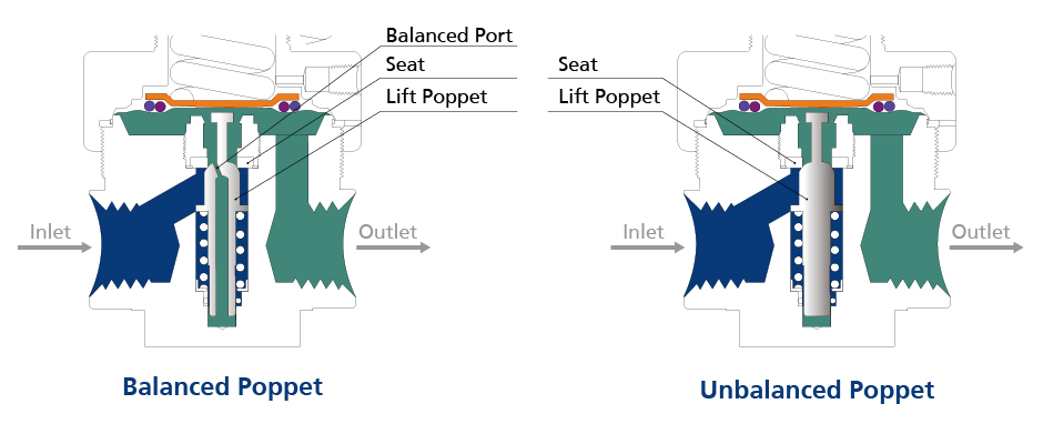
Figure 3 Balanced and Unbalanced Poppet Structures
Self-Venting: A feature of pressure regulators. By adding a path across the sensing mechanism, the regulator can fully release the outlet pressure in a contained system through the self-venting mechanism when the handle is turned counterclockwise (DECREASE). This eliminates the need for an additional purge or bleed valve. Refer to Pressure Regulator Explained (Ⅳ): Introduction to Regulators’ Venting Features for details.
Captured Venting: A feature of pressure regulators. By configuring a port to the bonnet, leaked media can be vented to a designated location when the sensing mechanism seal fails. Refer to Pressure Regulator Explained (Ⅳ): Introduction to Regulators’ Venting Features for details.

Parameters
Maximum Working Pressure: The maximum allowable pressure at the regulator’s inlet.
Outlet Pressure Range: The ranges of outlet pressures that the regulator can regulate, which can be specified during product selection.
Flow Coefficient (Cv): Defined as the volume of water (at 60°F or 16 ℃) that will flow through the regulator per minute with a pressure drop of 1 psi across the regulator. For gaseous service, Cv can also be calculated using a relevant formula. Cv is measured when the regulator is fully open and corresponds to the choked flow section of the flow curve. It is not recommended to use Cv as the primary selection criterion for regulators.
Supply Pressure Effect (SPE): Also known as decaying inlet characteristic, the SPE refers to the phenomenon where a change in the inlet pressure causes a corresponding change in the outlet pressure, meaning that as the inlet pressure increases, the outlet pressure will decrease, and vice versa. The SPE is a fixed value provided by the manufacturer.
Leak Rate (Helium): Leakage testing using helium as the test medium.
Leak Rate (Helium)—Inboard: Test for leakage from outside into the regulator using helium as the test medium. Refer to High Purity Valve Leak Testing for details.
Leak Rate (Helium)—Outboard: Test for leakage from inside the regulator to the outside using helium as the test medium. Refer to High Purity Valve Leak Testing for details.
Leak Rate (Helium)—Internal: Test for leakage from the regulator seat when it is closed, using helium as the test medium. Refer to High Purity Valve Leak Testing for details.
Flow Curve: A graphic representation that shows how the outlet pressure changes with varying flow rates. The horizontal axis represents flow rate, while the vertical axis shows outlet pressure. The flow curve is a primary reference when selecting pressure regulators. Refer to Pressure Regulator Explained (III): How to Use a Pressure Regulator Flow Chart for details.
Droop: The flow curve is not a straight horizontal line; instead, it gradually declines as the flow rate increases, as depicted in the flow curve chart. The extent of drop varies depending on the regulator series.
Initial Droop: Install a preset pressure regulator on the pipeline and open the downstream shutoff valve to enable medium flow in the pipeline. At this point, a sudden medium flow can cause an imbalance in the regulator, leading to a sharp drop in pressure. Pressure regulators are not recommended to be used for this section.
Ideal Operating Range: Also known as optimal flow range. Within this section, the flow curve is smooth, with no abrupt changes. This is the range where the internal components of the regulator are in force equilibrium. This section is the recommended operating range for pressure regulators.
Choked Flow Range: The flow curve exhibits a distinct turning point, indicating that the regulator is fully open at this stage. In this section, the regulator is no longer regulating the pressure. Figure 4 displays a typical flow curve, through which we can visually understand droop, initial droop, ideal operating range, and choked flow range.
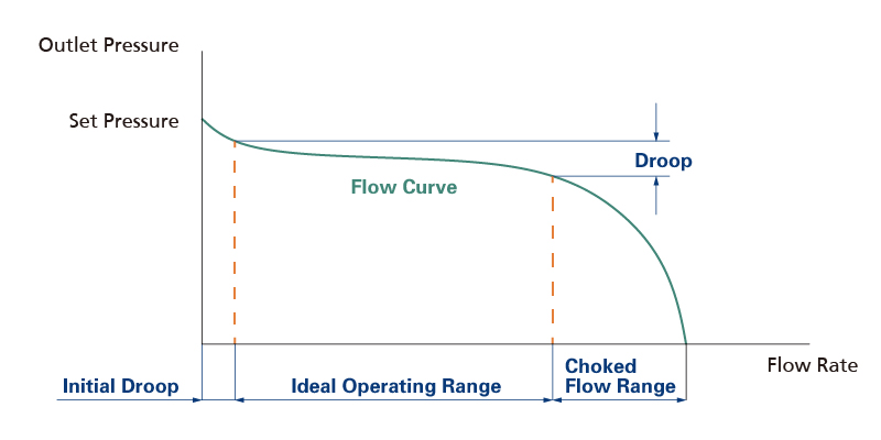
Figure 4 Typical Flow Curve of Pressure Regulator
Lock Up: When the valve downstream of the pressure regulator controls the medium flow and the flow gradually decreases to zero, the regulator closes, and the outlet pressure is slightly above the set pressure. This phenomenon is known as lock up.
Hysteresis: The outlet pressure of a pressure regulator is not only related to current operating conditions but also influenced by the direction in which the set value is adjusted. When the regulator is adjusted in the increasing and decreasing flow directions, the corresponding outlet pressure at the same flow rate may differ (Figure 5). However, hysteresis generally does not impact the normal operation of pressure regulators.
Creep: Any increase in outlet pressure after the regulator closes. Distinct creep should be deemed as internal leakage.
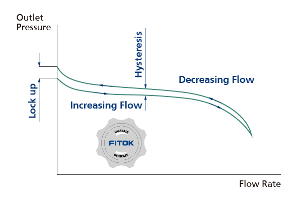
Figure 5 Flow Curve of Pressure Regulator (Hysteresis)
Related Articles: