Proper Orientation of Needle Valves Installed On Sampling Assemblies
As industrial production processes become increasingly complex, the standards for sample analysis grow more stringent, with a greater emphasis on safe sampling. Consequently, sampling systems have evolved from simple, rudimentary methods to safe and reliable grab sampling techniques. FITOK sampling systems are classified into two types based on the sample container: bottle configuration and cylinder configuration. Bottle configuration sampling systems collect samples into containers under normal pressure, while cylinder configuration sampling systems collect samples into containers under process pressure. Sampling assemblies are a crucial component of cylinder configuration sampling systems, designed for the sampling of liquefied gases, liquids, and gases that are characterized by high temperature, high pressure, corrosiveness, toxicity, high volatility, and environmental harm. They are widely used in various fields such as chemistry, petroleum, pharmaceuticals, and environmental protection.


Most Proper Orientation for Installing Needle Valves on Sampling Assemblies
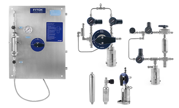
Sampling assemblies primarily consist of sample cylinders, needle valves, and quick-connects. They can be customized to meet specific customer needs. Needle valves are typically installed at both ends of the sample cylinder to control the flow of media in and out of the cylinder. Generally, needle valves are installed with the inlet connected to the cylinder and the outlet connected to a quick-connect (i.e., with the flow arrow pointing away from the cylinder). Therefore, some people may wonder why needle valves are installed in a direction away from the cylinder (indicated by the flow arrow), instead of pointing towards the cylinder or in another direction.

The Structure of FITOK Sampling Assemblies
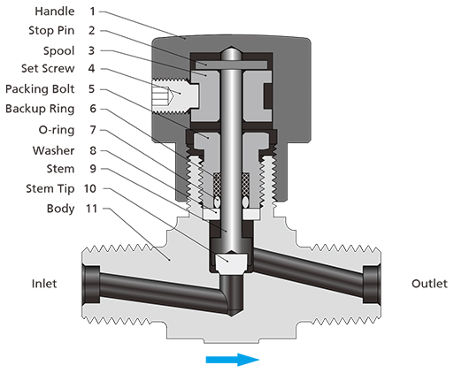
Before answering this question, let's first understand the basic structure of a needle valve. The flow of fluid is controlled by the opening and closing action between the stem tip and the seat, with the stem tip and stem rising and falling as the handle is rotated. In this process, the most vulnerable point for fluid leakage is the stem seal. Therefore, to ensure that the valve does not leak, structures such as washer, O-ring, backup ring, and packing bolt are installed between the stem and handle to achieve maximum sealing effectiveness. However, even with these measures in place, when the valve is in a closed state, compared to its inlet section, there is still a higher likelihood of leakage in the space connected to the stem (i.e., its outlet section). When pressure exists on the bottom surface of the seat (inlet section), valves are typically most effective at containing pressure while minimizing stem leakage.

The Structure of FITOK ND Series Needle Valves
Now let's go back to the original question: why is the installation direction for a needle valve (the flow arrow) directed away from the cylinder? First, we need to understand that the main function of a sampling assembly is to transport collected samples to the laboratory safely and without leaks, with cylinder valves remaining in the closed position after sampling systems have collected the samples. In other words, sampling assemblies should store medium under certain pressure for transportation. Therefore, the needle valve connected to the cylinder must have excellent sealing performance to ensure that the medium inside does not leak. From our understanding of the basic structure of a needle valve mentioned above, we know that in its closed state, the sealing performance in the inlet section is optimal. Consequently, for optimal installation, it is recommended that the inlet be connected with the cylinder, with the flow arrow pointing away from it.

FITOK Sampling Systems and Sampling Assemblies
FITOK boasts extensive experience in designing and manufacturing sampling systems. We offer a wide selection of series and models, as well as customizable designs tailored to customer needs and specific working conditions to meet customer needs as much as possible.
Highlights of FITOK Sampling Systems
- With a wealth of experience in sampling systems, we provide customizable designs tailored to customer needs and actual working conditions, as well as one-stop solutions including system design, assembly, training, filed service, and spare parts supply, etc.
- Key components, such as sample cylinders, needle valves, quick-connects, fittings, hoses, tubing, and coolers, are all manufactured and tested in FITOK’s factory. Superior product quality ensures reliable and safe sampling systems.
- With sufficient inventory of raw materials and finished products, FITOK ensures swift delivery.
- Material options include 316L stainless steel, 2507 super duplex steel, Hastelloy and Inconel, etc. Materials that meet NACE MR0175 standards are available for sour service.
- Welding procedure (WPS/QPR/WQT) has received approval from Lloyd's Register.
- Fittings used for FITOK sampling systems, such as 6D series tube fittings, have passed all standard tests and supplemental tests under ASTM F1387 standards.
- FITOK sample cylinders are designed and manufactured in compliance with 49 CFR regulations issued by the U.S. Department of Transportation, ensuring excellent safety, reliability, and extended service life. TPED and DOT cylinders are also available, with factory test reports provided for the complete set of sampling assemblies.
- Internally sandblasted cylinders provide smooth inner surfaces, reducing impurity residues and facilitating cleaning.
- SilcoNert® 2000 (Sulfinert®) coated cylinders are available, offering a stable passivation layer that withstands ppb-level sulfides and mercury in petroleum samples for extended storage periods.
Related Articles:


.jpg)
.jpg)
 Back
Back 

