Two-Step Pneumatic Diaphragm Valves Explained

Background
The semiconductor industry demands high cleanliness standards for pipelines, process equipment cavities, etc. For processes like etching and deposition, not only the cavity is required to be vacuumed to a certain degree, but also the reaction chamber must meet strict requirements for its environment.
When media flow rapidly into the process equipment cavity, the pressure inside the cavity surges, and particles are scattered, contaminating the cavity. To address this issue, the traditional way is to add a bypass pipeline next to the main pipeline. This bypass pipeline is composed of a metering valve and a normally closed (NC) pneumatic diaphragm valve, of which the former regulates the flow, while the latter controls the opening and closing of the pipeline.
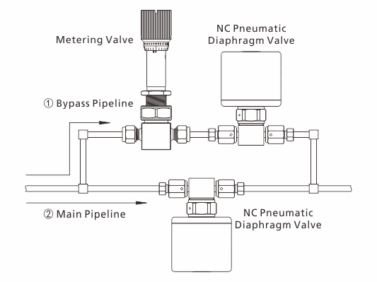
1. When the gas pressure inside the pipeline is higher than the cavity, open the NC pneumatic diaphragm valve to access the bypass pipeline. Then use the front metering valve to regulate the flow.
2. When the cavity pressure gradually increases up to a certain point, close the bypass pipeline and switch to the main pipeline.
Through the switching between the main pipeline and the bypass pipeline, the cavity pressure rise is alleviated, achieving a “soft start” of the equipment. Although the traditional way may address the issue of rapid flow of media into the cavity, it has some problems as follows:
1. Space occupied by two pipelines.
2. Complicated pipelines leading to more potential leak points and higher operating costs.
3. The metering valve controls the medium flow with a needle stem, however, in high purity applications, the machined stems and the inaccurate alignment between the stem and valve channel are likely to generate particles, which contaminate high purity media and may damage pipeline components.
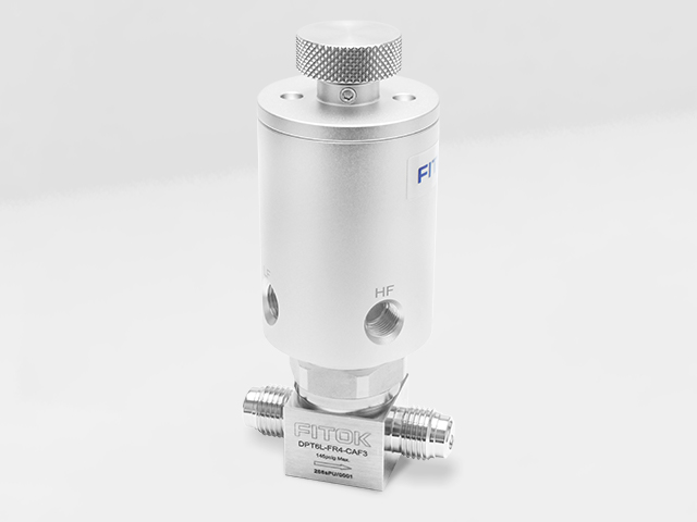
Is there a better solution for achieving the “soft start”? Here come the FITOK DPT series two-step pneumatic diaphragm valves.

Two-step Pneumatic Diaphragm Valves DPT Series
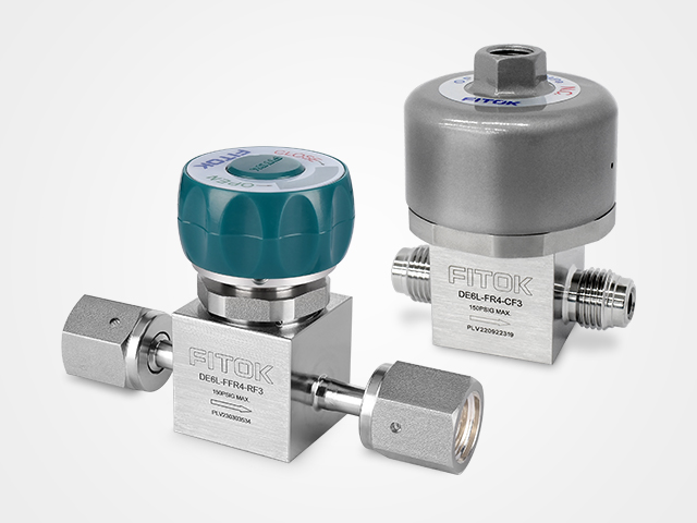
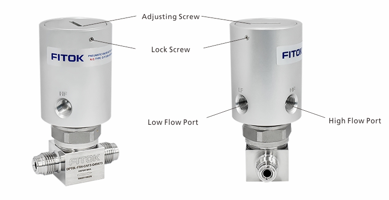
FITOK two-step pneumatic diaphragm valves, intended for high purity and ultra high purity applications, can switch rapidly between low flow and high flow rates to realize the “soft start” of the equipment. They are applicable to scenarios requiring different flow rates, with a working pressure of vacuum to 145 psig and wetted surface roughness up to Ra 0.13 μm.
1. Low flow (LF) port: In the low flow mode, the diaphragm opens in a limited manner, resulting in a small valve flow coefficient (Cv = 0.02 ~ 0.12);
2. High flow (HF) port: In the high flow mode, the diaphragm opens completely, allowing for maximum valve flow coefficient (Cv = 0.27).
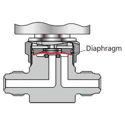
Supply air to corresponding low or high flow ports of the pneumatic actuator respectively as per required flow rates. The actuator will then control the diaphragm valve to operate in corresponding low or high flow modes. The Cv value of the valve in low flow mode can either be preset at the factory according to user-specified values, or it can be set by the users themselves based on the process parameters.
Technical Data
| Port Size | 1/4" | |
| Flow Coefficient (Cv) | High-Flow (HF) Port: 0.27 Low-Flow (LF) Port: 0.02 ~ 0.12 |
|
| Orifice Size | 0.16 in. (4.1 mm) | |
| Working Pressure | Vacuum to 145 psig (10 bar) | |
| Pneumatic Actuator Working Pressure | 79.75 ~ 94.25 psig (5.5 ~ 6.5 bar) | |
| Working Temperature | PFA: 14 ~ 302 °F (-10 ~ 150 °C) PCTFE: 14 ~ 176 °F (-10 ~ 80 °C) |
|
| Leak Rate (Helium) | Internal | ≤ 1×10⁻⁹ std cm3/s |
| External | ≤ 1×10⁻⁹ std cm3/s | |
Flow Data
Air @ 21 °C (70 °F)
Water @ 16 °C (60 °F)
| Orifice in. (mm) |
Pressure Drop to Atmosphere psig (bar) |
Air (l/min) |
Water (l/min) |
| 0.16 (4.1) | 10 (0.68) | 86 | 3.2 |
| 50 (3.4) | 230 | 7.2 | |
| 100 (6.8) | 410 | 10.2 | |
相关文章:


.jpg)
.jpg)
 Back
Back 